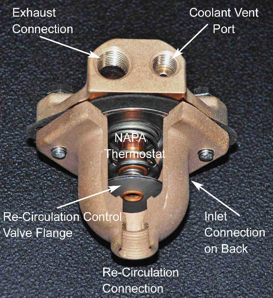
Bronze Fresh Water Cooled (FWC) Thermostat with section removed to show internal Components.

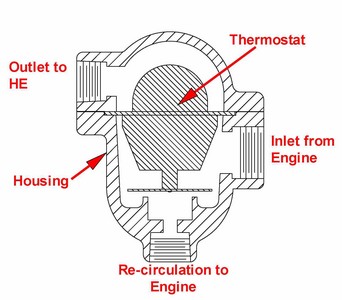
So how is the Indigo FWC Thermostat different? As can be seen in the drawing to the right, the Indigo Thermostat includes both the actual thermostat and a totally separate thermostat housing. This kit utilizes a "double-action" thermostat but in this case, the "double-action" aspect controls antifreeze that is re-circulated to the engine instead of controlling antifreeze that is by-passed around the block as the original thermostat does. The housing assembly can be mounted in several locations depending on your engine compartment layout. The easiest location is where the antifreeze exits the manifold (typically the end near the transmission but it can go on the flywheel end with a little re-routing of hoses) or on a bulkhead near the engine. With this new thermostat installed, the original one, either the "Dole" or "Holley" model is removed. In the case of the "Holley", the existing thermostat housing is reused (even with a corroded control surface) and the original bypass hose is plugged.
For a FWC engine, some new plumbing is required to properly configure the Indigo Thermostat. This involves the "re-circulation" connection. When the engine is running, a portion of the antifreeze flow (controlled by the re-circulation flange on the bottom of the thermostat) passes through the block, head and manifold and then back to the suction side of the antifreeze pump. A hose must be run from this re-circulation connection to a new tee which must be installed at the suction or inlet side of the antifreeze pump. Installation Hardware Packages (see below) are available which provide all of the necessary fittings for making the plumbing changes described above. You will still need to provide the hoses.
Fresh Water Cooled (Antifreeze) Performance - Both Mechanical and Electric Systems
Thermostat control in a FWC application is a very straight forward engineering problem. The thermostat itself has the ability to control antifreeze re-circulation flow back to the antifreeze pump and antifreeze flow through the engine to the heat exchanger for cooling to limit engine temperature to 180°F . Raw water to the exhaust is uncontrolled and always at maximum flow ensuring that the exhaust system is always very cool. A "Jiggle Pin" vent hole has been added to the thermostat flange to both vent the system of any trapped air and also to improve stability in low raw water temperature conditions. In such cold raw water environments, 50 - 70°F, the engine temperature will not fully reach 180°F at low power levels as the antifreeze flow through the vent hole is almost sufficient to satisfy the cooling requirements of the engine. The following data shows performance of the FWC application with 80°F raw water:
| Engine RPM Under Load at Dock |
Temperature Gauge Reading |
Coolant Out of Thermostat |
Coolant Into Block |
| 1200 |
172F |
168F |
146F |
| 1600 |
176F |
171F |
138F |
| 2000 |
185F |
177F |
134F |
| 2150 (WOT) |
187F |
178F |
132F |
NOTE 1: An interesting observation was made during testing. The temperature read by the traditional "in-head" sensor (shown in above chart as "Temperature Gauge Reading") was always several degrees higher than the temperature of the actual coolant. The difference is a function of engine load and is most likely attributable to heat being transferred through the metal of the head directly to the sensor. A significant benefit of the Indigo Thermostat Kit is that it allows the traditional temperature sensor to be re-located to the coolant entrance to the new thermostat. This not only gives a more accurate indication of engine coolant temperature but it also frees up the "in-head" connection for the installation for a high temperature alarm sensor. Check out our Alarm Kit which is a great addition for peace of mind when motoring. Having each of the two temperature sensors in an active coolant flow area is a far superior installaton as compared to the common practice of installing the two in a "dead headed" tee on the head.
Click on the links below to see coolant flow in a FWC installation and Installation Instructions
Thermostat Coolant Flow in FWC System
Download Thermostat Installation Instructions for a Mechanical Antifreeze Pump
Download Thermostat Installation Instructions for an Electric Antifreeze Pump
- A Complete Retrofit Package including:
- Step-by-step instructions
- Precision cast and machined Silicon Bronze housing
- Drilled and tapped connections to:
- Mount housing on manifold.
- Accept re-circulation hose.
- Accept exhaust coolant hose.
- Vent antifreeze loop at thermostat.
- 160F or 180F Thermostats for FWC .
- Gaskets, housing fasteners, and existing bypass blank-off fitting included.
Installation Hardware Packages
FRESH WATER COOLING - MECHANICAL PUMP: Includes one 1/2 NPT tee to attach thermostat housing to manifold, a 1/2 NPT pipe plug for the "empty" leg on the tee, one hose barb fitting for the thermostat re-circulation connection, one 3/8 NPT tee with 3/8 NPTclose nipple for the antifreeze pump suction, one hose barb fitting for the re-circulation connection at the previous tee, one hose barb fitting for the heat exchanger connection on the thermostat, and three all stainless hose clamps. No hose is provided. PRICE: $30.00
FRESH WATER COOLING - ELECTRIC PUMP: Includes one 1/2 NPT tee to attach thermostat housing to manifold, a 1/2 NPT pipe plug for the "empty" leg on the tee, one hose barb fitting for the thermostat re-circulation connection, one 1/2 NPT tee and 1/2 close nipple for the antifreeze pump suction, one hose barb fitting for the re-circulation connection at the previous tee, one hose barb fitting for the heat exchanger connection on the thermostat, and three all stainless hose clamps. No hose is provided. PRICE: $42.00
Indigo Electronics, Inc.
105 Pipe Kiln CourtWilliamsburg, VA 23185